SPI Receive Block
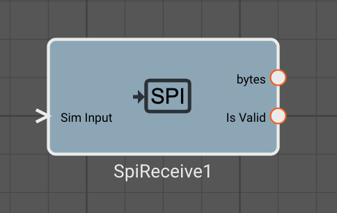
The SPI Receive Block reads 8 or 16 bit data from an SPI device. Currently each SPI bus can control one SPI peripheral each. The SPI Receive Block will de-assert the Chip Select pin at the end of the read operation.
Inputs
- Sim Input - An array of bytes used for simulating data from a peripheral
Parameters (STM32)
- Spi (default = SPI1): SPI device to transmit data on
- Sck (default = PA5): Pin used for the SPI clock
- Mosi (default = PA7): Pin used for master out, slave in
- Miso (default = PA6): Pin used for master in, slave out
- Cs (default = PA0): Pin used for Chip Select
Parameters (Linux)
- Port (default = /dev/spidev0.0): SPI device
- Cs Pin (default = 0): Pin used for Chip Select
Parameters (common)
- Mode (default = 0): The configuration of the SPI device. These dictate the phase and polarity of the clock in relation to the data. See here for more details. Mode 0, 1 , 2, 3 have been implemented on Linux and STM32 devices.
- Bit Order (default = "MSB First"): Determines the BIT order of the data. Most Significant Bit First and Least Significant Bit First are available.
- Bits per Transfer (default = 8): Determines the number of bits that are written per transfer.
- Read Fixed Bytes (default = 1): The number of bytes to read from the SPI bus, must be less than the buffer size of 256 bytes
- Stale Age (default = 1000): Flag used to indicate the time before the buffer is marked stale, if so the "Is Valid" pin is low.