True and False in a Floating Point World
As described in Computation in Pictorus, data that flows between blocks are represented as 64-bit floating point values. Blocks that operate on Boolean logic values convert floating point to truth values thus
- False is exactly zero
- True is any non-zero value
Boolean outputs are
- Exactly 0 for False
- Exactly 1 for True
Converting from calculated floating point values to Boolean logic values can be tricky because expressions that are equal for real numbers may only be approximately equal for fixed-precision floating point values. Moreover, due to sampling error, it is possible to "miss" a point on a continuous function. The examples below illustrate some of the challenges and solutions.
Simple Control Example
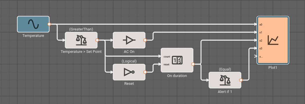
Consider a simple air conditioner control application. The air conditioner should turn on only when the temperature is greater than a set point of 70°. We can use a Compare To Value block. We model the temperature with a Sinewave. As a visualization aid, we multiply the comparitor output by 100 with a Gain block (AC On in the figure below).
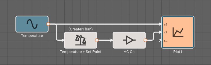
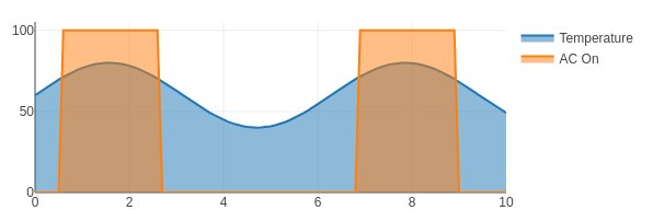
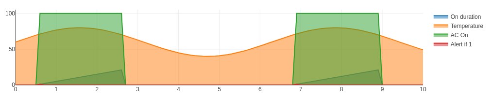
The Plot below shows temperature in blue and the air conditioner on state in orange.
Alert Example
Suppose an alert tone is required when the air conditioner turns on. Ideally, we could use another Compare To Value block to test whether or not the temperature is equal to the set point.
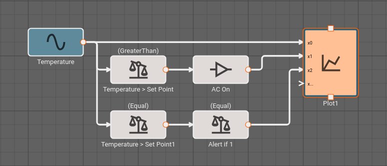
If we try this, we discover it doesn't work! The temperature is exactly 70° in between time steps; none of the samples is exactly equal to the set point, so the alert signal is always False and no alert is ever generated.
If we had been unlucky with our choice of model parameters, the application might have appeared to work. There's another defect. If we could successfully test that the temperature exactly equals the set point, the alert would play both when air conditioner turned on and when it turned off.
To repair both defects, we cannot simply change the condition to GreaterThanOrEqual, because the alert would play over and over. We can, however, use a Counter block. As long as the temperature is greater than or equal to the set point, increment the counter once per time step. Only when the counter is exactly one, play an alert. When the temperature is less than the set point, reset the counter.
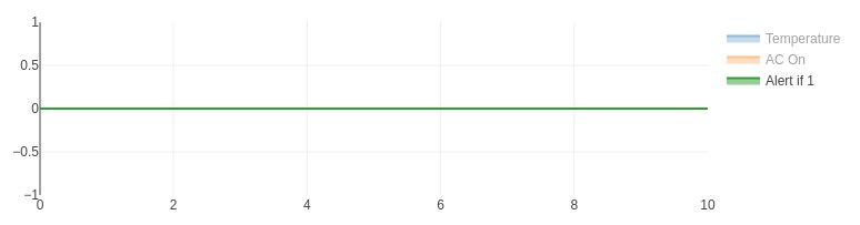
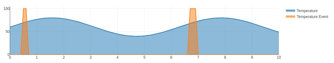
The alert signal is not visible when all the signals are plotted because it is relatively small, with a magnitude of one corresponding to True.
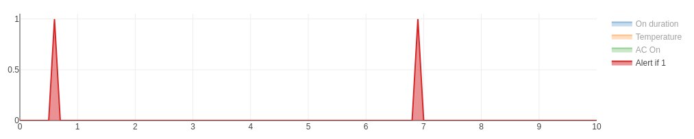
If we hide the other signals, the alert signal is visible as a pair of spikes that occur when the temperature is rising above 70°.
Safely testing Boolean conditions on continuous signals
As the example above illustrates, we cannot assume that a signal that crosses a threshold will be sampled exactly at the point it crosses the threshold.
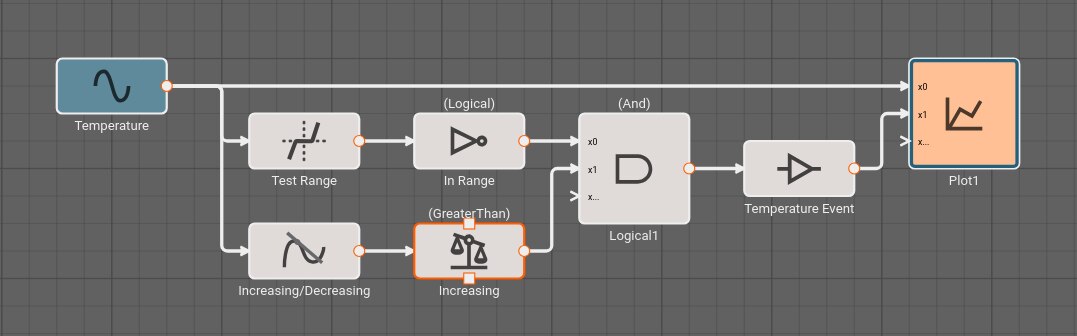
It's often better to test inclusion in a range than strict equality. The Deadband block provides a range test. This is another way to reliably obtain a Boolean value from an arbitary signal. In the example above, we could trigger our alert when the temperature is within a range including the set point, and the input signal is increasing. The Derivative is positive when the signal is increasing. Because the deadband is False when the signal is in the range, a Not is needed.
Differences from the previous example.
If the signal begins above the threshold, no initial event will be detected.
The alert signal remains 1 as long as the temperature remains in the range; in the previous example the alert signal is only 1 for a single time step after the signal exceeds the set point.